
Frage an die Schaltplanspezialisten
47 Beiträge
• Seite 2 von 4 • 1, 2, 3, 4
Re: Frage an die Schaltplanspezialisten
![]() von Herbert H » Di 10 Mär, 2020 11:06
von Herbert H » Di 10 Mär, 2020 11:06
Oder wie bei den Alten Italiener. Wechsel Spannung an den Lampen . Wird geregelt über den Lastwiderstand der Lampen. Zweiter Stromkreis für Blinker Batterie und Standlicht mit Regelung.
- Herbert H
- Wenigschreiber
- Beiträge: 872
- Registriert: Do 18 Jun, 2015 15:00
Re: Frage an die Schaltplanspezialisten
![]() von hiha » Di 10 Mär, 2020 12:26
von hiha » Di 10 Mär, 2020 12:26
@KNEPTA
Die Lösung für die GN mit dem Rollerregler und einem als Hubdiode geschalteten Brückengleichrichter kennst Du aber schon, oder?
Ist billiger wie ein RöbiRegler, den Du aber auch 1:1 anschließen kannst.
Ich such mal die Skizze für die GN-Lösung raus.
Gruß
Hans
Die Lösung für die GN mit dem Rollerregler und einem als Hubdiode geschalteten Brückengleichrichter kennst Du aber schon, oder?
Ist billiger wie ein RöbiRegler, den Du aber auch 1:1 anschließen kannst.
Ich such mal die Skizze für die GN-Lösung raus.
Gruß
Hans
"Im Übrigen bin ich der Ansicht, dass Profifußball verboten werden muss."
-
hiha - Älterer Herr und Motorenkenner
- Beiträge: 17560
- Registriert: Fr 28 Okt, 2005 10:01
- Wohnort: Neubiberg b. München
Re: Frage an die Schaltplanspezialisten
![]() von gatsch.hupfa » Di 10 Mär, 2020 17:27
von gatsch.hupfa » Di 10 Mär, 2020 17:27
Wenn du die verbesserte Variante vom Hasn nicht willst:
Die Regelei der SP scheint ganz ähnlich zu sein wie von den 2V XT 500ern.
Und daher stellt sich das der kleine tom so vor:
Die W/Bl Leitung von der Lichtspule soll über die Diode den Gleichstromkreis der Batterie versorgen.
Die P Leitung, angeschlossen irgendwo kurz vor dem Ende der Lichtspule damit weniger Spannung induziert wird als auf der W/Bl Leitung, soll die unter Wechselstrom laufenden Verbraucher (haupsächlich Scheinwerfer) versorgen.
Über den Lichtschalter wird der Regler entweder an den Lichtkreis oder an den Batteriekreis gelegt.
Licht eingeschaltet:
Die Leitung P (nach dem Stecker: Y/R) wird über den Lichtschalter mit den Lichtverbrauchern UND dem Regler über Gr verbunden.
Die Leitung W/Bl (nach dem Stecker heisst dir Y/W) wird über den Lichtschalter auf W/R geschaltet und geht direkt zur Diode.
Sinn des ganzen ist meiner Meinung nach, dass der hohe Strom durch die Scheinwerfer die Lima/ Verdrahtung/ Schalter sehr belastet. Und somit die Spannung leichter einbricht durch die ganzen Übergangswiderstände. Damit doch noch ein bisserl mehr an der Diode / Batterie ankommt, wird also die Anzapfung geregelt, damit am End der Spule Überspannung rauskommt.
Licht ausgeschaltet: P wird über den Lichtschalter getrennt, somit hängt der Regler nicht mehr an P. Es fliessen auch keine hohen Ströme, die bei einem gegebenen Leitungswiderstand (z.B. auch die gemeinsame Masseleitung der 2 Kreise) viel Spannung abfallen lassen.
Dafür sollte jetzt aber die Leitung W/Bl für den Gleichstromkreis geregelt werden.
Dafür muss die Leitung W/Bl SOWOHL mit der Leitung G/W als auch mit der Leitung G/W von deinem alten Regler verbunden sein!
Im Auszustand verbindet der Lichtschalter jetzt die Leitung G/W vom Regler weg mit der Leitung zur Diode (W/R).
Das bezieht sich alles auf deinen 2. Schaltplan und dem alten Regler.
Beim Schaltplan 1 interpretiere ich das so, dass es Mopedvarianten gibt, wo das Licht immer eingeschalten ist. Dafür reicht dann natürlich auch ein Regler mit nur einem Eingang (Grau).
Also schalt das Licht nie aus beim neuen Regler, sonst kocht die Batterie bald über wenn du nur G/W an W/Bl hängst, was wahrscheinlich im Kabelbaum schon so verdrahtet ist, und die G/W zum nicht mehr vorhandenen 2. Anschluss des Reglers offenlässt.
Oder du durchtrennst die G/W Leitung, die zum Lichtschalter führt, dann lädt die Batterie nur bei eingeschaltetem Licht.
Oder du besorgst dir einen Regler mit 2 Anschlüssen.
Ich hoff, es ist noch keiner eingeschlafen.
-

gatsch.hupfa - Vielschreiber
- Beiträge: 2503
- Registriert: Di 20 Jan, 2015 14:38
- Wohnort: südlich von Wien
Re: Frage an die Schaltplanspezialisten
![]() von Herbert H » Di 10 Mär, 2020 17:36
von Herbert H » Di 10 Mär, 2020 17:36
Die ZDiode kann nicht viel überschüssige Spannung verheizen. Darum wurde der Stromkreis aufgeteilt.
- Herbert H
- Wenigschreiber
- Beiträge: 872
- Registriert: Do 18 Jun, 2015 15:00
Re: Frage an die Schaltplanspezialisten
![]() von hiha » Di 10 Mär, 2020 18:04
von hiha » Di 10 Mär, 2020 18:04
Drum nimmt man dafür heut keine ZDioden mehr für diesen Zweck, sondern sowas wie ein sog. CrowBar, mit Thyristor oder Triac.
Gruß
Hans
Gruß
Hans
"Im Übrigen bin ich der Ansicht, dass Profifußball verboten werden muss."
-
hiha - Älterer Herr und Motorenkenner
- Beiträge: 17560
- Registriert: Fr 28 Okt, 2005 10:01
- Wohnort: Neubiberg b. München
Re: Frage an die Schaltplanspezialisten
![]() von gatsch.hupfa » Di 10 Mär, 2020 18:18
von gatsch.hupfa » Di 10 Mär, 2020 18:18
Herbert H hat geschrieben:Die ZDiode kann nicht viel überschüssige Spannung verheizen. Darum wurde der Stromkreis aufgeteilt.
Versteh ich nicht.
Wenn Licht aus, dann muss er sogar die volle Spulenlänge niederregeln.
-
gatsch.hupfa - Vielschreiber
- Beiträge: 2503
- Registriert: Di 20 Jan, 2015 14:38
- Wohnort: südlich von Wien
Re: Frage an die Schaltplanspezialisten
![]() von lallemang » Di 10 Mär, 2020 18:50
von lallemang » Di 10 Mär, 2020 18:50
In Plan1 wie 2 ist Grau nur bei Licht-An angeschlossen. Der Rest ist alles ungeregelt/batteriegepuffert.
Z-Dioden mit Leistung sind teuer. (Die Commando hat so eine als Gesamtregelung und die wird so hei§ wie ihr Preis ist )
)
Z-Dioden mit Leistung sind teuer. (Die Commando hat so eine als Gesamtregelung und die wird so hei§ wie ihr Preis ist
Wherever You Go There You Are 
-

lallemang - Moderator
- Beiträge: 17573
- Registriert: Mo 10 Apr, 2006 01:18
- Wohnort: im Osten des Südwesten
Re: Frage an die Schaltplanspezialisten
![]() von motorang » Mi 11 Mär, 2020 12:19
von motorang » Mi 11 Mär, 2020 12:19
So,
hier einmal die beiden Anhänge aus Beitrag 1 direkt klickbar
Anhang 1 Schaltplan SP370 aus dem Werkstatthandbuch:
Anhang 2: Die reine Reglerseite schaut wohl so aus (SP370)
Im Werkstatthandbuch der SP370 steht auch was zum Regler:
Der Schaltplan der Sp370 zeigt neben dem Regleranschluss auch einen unbelegten Anschluss, der wohl im Kabelbaum vorhanden aber nicht verwendet ist. Er gehört nach Forenbeiträgen zu einem Widerstand, der als magneto resister oder balast resistor oder ähnlich bezeichnet wird:
https://www.tapatalk.com/groups/dr400/s ... -t358.html
Zumindest bei der ähnlichen DR400 scheinen BEIDE Komponenten gleichzeitig verbaut worden zu sein.
Hier > https://www.cmsnl.com/suzuki-sp370-1978 ... 651032412/ Originalnummer 36510-32412
Und so schauts aus:
Die SP400 hat dieses Setup aus dem Schaltplan der SP370 auch im Werkstatthandbuch beschrieben:
Das System ist ähnlich aber nicht gleich wie bei der XT500.
Der Lastwiderstand ist bei der SP400 also dazu da, den Strom zu verbrauchen, den dann die Beleuchtung gerade NICHT verbraucht. Weil sonst die Bordspannung bei ausgeschaltetem Licht so weit nach oben ginge, dass die Batterie bald stürbe (:D). Regelung durch Last, funktioniert halbwegs so lange die Last stimmt (zB die Scheinwerferbirn die richtigen Watt hat, keiner was auf LED umbaut, oder die Scheinwerferbirn nicht durchbrennt).
Der Regler der SP370 sorgt aber schon durch die Spannungsregelung dafür dass die Spannung nicht zu hoch wird - beides gleichzeitig braucht's nicht ... WENN das entsprechend verkabelt und verschalten ist. Ist die Schaltung aber so wie bei der SP400, dann müssen die beiden offenen Anschlüsse verbunden werden sonst fließt bei "Licht aus" kein Strom zur Batterie.
In diesem englischsprachigen Forenthema werden Handbücher analysiert (u.a. der amerikanische Clymer) und anscheinend hatte die amerikanische Version den Widerstand eingebaut, die englische Version aber nicht.
@Uwe: Der Originalregler hat nur einen Anschluss. Womit ist denn der zweite Anschluss an Deinem davor eingebauten Regler verbunden gewesen? ... Steht auf dem Regler was drauf so dass man forschen könnte? Eventuell ist der zweite Anschluss nur für Masse, die der originale Regler über die Gehäuseverschraubung bekommt.
Gryße!
Andreas, der motorang
hier einmal die beiden Anhänge aus Beitrag 1 direkt klickbar
Anhang 1 Schaltplan SP370 aus dem Werkstatthandbuch:
Anhang 2: Die reine Reglerseite schaut wohl so aus (SP370)
Im Werkstatthandbuch der SP370 steht auch was zum Regler:
- sp370_regelung_3.jpg (100.59 KiB) 2798-mal betrachtet
Der Schaltplan der Sp370 zeigt neben dem Regleranschluss auch einen unbelegten Anschluss, der wohl im Kabelbaum vorhanden aber nicht verwendet ist. Er gehört nach Forenbeiträgen zu einem Widerstand, der als magneto resister oder balast resistor oder ähnlich bezeichnet wird:
https://www.tapatalk.com/groups/dr400/s ... -t358.html
Zumindest bei der ähnlichen DR400 scheinen BEIDE Komponenten gleichzeitig verbaut worden zu sein.
Hier > https://www.cmsnl.com/suzuki-sp370-1978 ... 651032412/ Originalnummer 36510-32412
Und so schauts aus:
Die SP400 hat dieses Setup aus dem Schaltplan der SP370 auch im Werkstatthandbuch beschrieben:
Das System ist ähnlich aber nicht gleich wie bei der XT500.
- Bei der XT500 wird bei eingeschaltetem Scheinwerfer die Lichtspule geregelt, bei ausgeschaltetem Licht die Ladespule (bzw jeweils der entsprechende Wicklungsteil), das beeinflusst aber jeweils auch den "ungeregelten" Spulenteil. Es wird also der Regler umgeschaltet.
- Bei der SP400:
Bei ausgeschaltetem Scheinwerfer ("day") wird ein Teil des Stroms über den Lastwiderstand verbraten,
der Rest geht über OHNE REGLER den Gleichrichter in die Batterie.
Bei eingeschaltetem Scheinwerfer ("night") wird ein Teil des Stroms über die Beleuchtung verbraten,
der Rest geht OHNE REGLER über den Gleichrichter in die Batterie. - Bei der SP370 scheint es (glaub ich) einen Kabelbaum für zwei Modelle zu geben, wobei immer ein Regler verbaut ist, aber nur fallweise ein Lastwiderstand?
Der Lastwiderstand ist bei der SP400 also dazu da, den Strom zu verbrauchen, den dann die Beleuchtung gerade NICHT verbraucht. Weil sonst die Bordspannung bei ausgeschaltetem Licht so weit nach oben ginge, dass die Batterie bald stürbe (:D). Regelung durch Last, funktioniert halbwegs so lange die Last stimmt (zB die Scheinwerferbirn die richtigen Watt hat, keiner was auf LED umbaut, oder die Scheinwerferbirn nicht durchbrennt).
Der Regler der SP370 sorgt aber schon durch die Spannungsregelung dafür dass die Spannung nicht zu hoch wird - beides gleichzeitig braucht's nicht ... WENN das entsprechend verkabelt und verschalten ist. Ist die Schaltung aber so wie bei der SP400, dann müssen die beiden offenen Anschlüsse verbunden werden sonst fließt bei "Licht aus" kein Strom zur Batterie.
In diesem englischsprachigen Forenthema werden Handbücher analysiert (u.a. der amerikanische Clymer) und anscheinend hatte die amerikanische Version den Widerstand eingebaut, die englische Version aber nicht.
thats the difference in a UK SP370 - there is no regulator. The grey wire ends in an open terminal on the UK SP370. Perhaps there is some inherent weakness in the design and that going to magneto resistor PLUS regulator was Suzuki's belt & braces solution
your uk sp370 diagram makes more sense regarding the smaller charging diagram i posted earlier and to my first post on the problem. my dr 400 is the same as you 370 diagram with the exception that the dr is cdi not points.
the resistor is placed in the diagram just above the magneto, and mine doesn't have the voltage regulator shown on the end of the grey wire.
so to speculate again, the two feeds off the magneto need to reach ground at some point to obtain 6v. if your lights are off, then only the rectified circuit will ground giving you 12v. to combat this, the resistor is switched in circuit to pull the voltage to 6v. this isn't a 'regulator', only a resistor. if the resistor fails open circuit then your battery will not charge when lights are off. if the resistor fails short circuit, then your battery will cook with 12v or the rectifier will blow.
with your lights on, both circuits are grounded, so there is no need for the resistor. however only the headlight and instrument lights are ac, so if they blow or become corroded they wont reach ground, so 12v goes through the remaining charge circuit, this time with the resistor switched out and cooking your battery or blowing the rectifier.
with a damaged rectifier or knackered battery your lights will blow every time they are turned on as there is no ground on the charge circuit so the lighting circuit goes to 12v.
i think what is needed is a belt and braces approach like you said mike.
if you fit one of these (toter ebay link) onto the end of that grey wire, as per the usa diagram i posted then i think all areas would be covered.
assuming your battery is ok, and your mag resistor is ok and all terminals are free from corrosion, then if your main beam should blow (possibley due to vibration) then the excess voltage that would appear would be dissipated away preventing voltage surges and damage to the rest of the system.
For info, my resistor reading is 5.6 ohms
the rectifier is 1.5 Mohms one way, open circuit the other.
@Uwe: Der Originalregler hat nur einen Anschluss. Womit ist denn der zweite Anschluss an Deinem davor eingebauten Regler verbunden gewesen? ... Steht auf dem Regler was drauf so dass man forschen könnte? Eventuell ist der zweite Anschluss nur für Masse, die der originale Regler über die Gehäuseverschraubung bekommt.
Gryße!
Andreas, der motorang
-------------------
Gerade als die Raupe dachte, die Welt würde untergehen, verwandelte sie sich in einen Schmetterling.
Gerade als die Raupe dachte, die Welt würde untergehen, verwandelte sie sich in einen Schmetterling.
-

motorang - Site Admin
- Beiträge: 22966
- Registriert: Do 09 Jun, 2005 08:49
- Wohnort: Graz
Re: Frage an die Schaltplanspezialisten
![]() von Herbert H » Mi 11 Mär, 2020 13:10
von Herbert H » Mi 11 Mär, 2020 13:10
Das moderne Regler mit höheren Strömen aushalten war ja nicht die Frage. Die Z Diode wird bei 14 Volt leitend, und bei ca 13,5 nicht leitend. Also wird die Spitze der Wechselspannung gekappt. Tyristor Regler wir bei erreichen von 14 Volt gezüchtet- Leitend, und erst bei Null Volt ausgeschaltet.Da wird die halbe Kurve kurzgeschlossen. Halbleiter die nur Ein Aus schalten produzieren wenig Wärme. Die Z Diode regelt, dadurch wird die Heiß.
- Herbert H
- Wenigschreiber
- Beiträge: 872
- Registriert: Do 18 Jun, 2015 15:00
Re: Frage an die Schaltplanspezialisten
![]() von KNEPTA » Mi 11 Mär, 2020 13:15
von KNEPTA » Mi 11 Mär, 2020 13:15
Sears
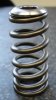
Das IST der alte derzeit noch verbaute Regler
download/file.php?id=13239&mode=viewl
Leider lieg ich derzeit auf Zimmer 244 und is Moped ist weit weg.
Auf jeden Fall ist ein Kabel des Reglers mit Grau verbunden und das andere mit Grün-weiß.
Das IST der alte derzeit noch verbaute Regler
download/file.php?id=13239&mode=viewl
Leider lieg ich derzeit auf Zimmer 244 und is Moped ist weit weg.
Auf jeden Fall ist ein Kabel des Reglers mit Grau verbunden und das andere mit Grün-weiß.
Russe und Salz, dann zerfallt´s !
Bdd. Ein Tag wie eine Woche.
Nix is gölber wie Gölb wie Gröllgölb sölber
Membää der KOG, Sektionsdirektor Alpen, Berge und Zeuch
Bdd. Ein Tag wie eine Woche.
Nix is gölber wie Gölb wie Gröllgölb sölber
Membää der KOG, Sektionsdirektor Alpen, Berge und Zeuch
-

KNEPTA - AiA Sektionschef
- Beiträge: 17479
- Registriert: Do 09 Jun, 2005 12:57
- Wohnort: Niklasdorf
Re: Frage an die Schaltplanspezialisten
![]() von lallemang » Mi 11 Mär, 2020 13:19
von lallemang » Mi 11 Mär, 2020 13:19
Egal wo Du bist, ich wünsch' Dir, da§ Du das auch geregelt kriegst 
Wherever You Go There You Are
-
lallemang - Moderator
- Beiträge: 17573
- Registriert: Mo 10 Apr, 2006 01:18
- Wohnort: im Osten des Südwesten
Re: Frage an die Schaltplanspezialisten
![]() von KNEPTA » Mi 11 Mär, 2020 13:45
von KNEPTA » Mi 11 Mär, 2020 13:45
Sch...so schaut der NEUE "originale" SP Regler aus...
https://www.ebay.com/p/9016721139
Is für die SP 500 und die GN 400
https://www.ebay.com/p/9016721139
Is für die SP 500 und die GN 400
Russe und Salz, dann zerfallt´s !
Bdd. Ein Tag wie eine Woche.
Nix is gölber wie Gölb wie Gröllgölb sölber
Membää der KOG, Sektionsdirektor Alpen, Berge und Zeuch
Bdd. Ein Tag wie eine Woche.
Nix is gölber wie Gölb wie Gröllgölb sölber
Membää der KOG, Sektionsdirektor Alpen, Berge und Zeuch
-
KNEPTA - AiA Sektionschef
- Beiträge: 17479
- Registriert: Do 09 Jun, 2005 12:57
- Wohnort: Niklasdorf
Re: Frage an die Schaltplanspezialisten
![]() von motorang » Mi 11 Mär, 2020 14:15
von motorang » Mi 11 Mär, 2020 14:15
Dann hast Du aktuell keinen Regler drin sondern den Lastwiderstand.
Der Regler wird schon passen, die SP500 ist auch ein 6V-Mopped ...
Die hier: https://www.regulatorrectifier.com/cata ... rectifiers ersetzen die Regler von GN400, SP370 und XT500 alle mit demselben Reglertyp ... SP500 ist leider nicht in der Liste.
Eigentlich sollte der Lastwiderstand an blau-weiß und grün-weiß hängen, und der Regler an grau.
Bei Dir "Die Kabel die zum verbauten Regler gehen sind grau und grün-weiß"
Wenn Du wieder zum Mopped kommst, schau mal ob Du ein blau-weißes Kabel hast das aus der Lichtmaschine kommt.
Dann könntest Du alles so zusammenstecken wie am Schaltplan ...
Gryße!
Andreas, der motorang
-------------------
Gerade als die Raupe dachte, die Welt würde untergehen, verwandelte sie sich in einen Schmetterling.
Gerade als die Raupe dachte, die Welt würde untergehen, verwandelte sie sich in einen Schmetterling.
-
motorang - Site Admin
- Beiträge: 22966
- Registriert: Do 09 Jun, 2005 08:49
- Wohnort: Graz
Re: Frage an die Schaltplanspezialisten
![]() von KNEPTA » Mi 11 Mär, 2020 14:16
von KNEPTA » Mi 11 Mär, 2020 14:16
https://www.ebay.com/p/9016721139
Noch gefunden...
Schaut so aus wie wenn das der Plan für mein Moped wär. Nur falsch zusamnengesteckt. Das graue Kabel hängt hier herum und zwischen den Steckern hängt der Widerstand drin.
Noch gefunden...
Schaut so aus wie wenn das der Plan für mein Moped wär. Nur falsch zusamnengesteckt. Das graue Kabel hängt hier herum und zwischen den Steckern hängt der Widerstand drin.
- Dateianhänge
-
Russe und Salz, dann zerfallt´s !
Bdd. Ein Tag wie eine Woche.
Nix is gölber wie Gölb wie Gröllgölb sölber
Membää der KOG, Sektionsdirektor Alpen, Berge und Zeuch
Bdd. Ein Tag wie eine Woche.
Nix is gölber wie Gölb wie Gröllgölb sölber
Membää der KOG, Sektionsdirektor Alpen, Berge und Zeuch
-
KNEPTA - AiA Sektionschef
- Beiträge: 17479
- Registriert: Do 09 Jun, 2005 12:57
- Wohnort: Niklasdorf
Re: Frage an die Schaltplanspezialisten
![]() von gatsch.hupfa » Mi 11 Mär, 2020 14:48
von gatsch.hupfa » Mi 11 Mär, 2020 14:48
KNEPTA hat geschrieben:
Schaut so aus wie wenn das der Plan für mein Moped wär. Nur falsch zusamnengesteckt. Das graue Kabel hängt hier herum und zwischen den Steckern hängt der Widerstand drin.
Nein, das ist glaub ich schon richtg zusammengesteckt auf deinem letzten Schaltplan.
Wie Andreas schrub, der Widerstand gehört zwischen W/Bl und G/W.
Und den Regler ans graue Kabel hängen wird nicht schaden.
Dann hast du wenigstens einen geregelten Lichtkreis.
-
gatsch.hupfa - Vielschreiber
- Beiträge: 2503
- Registriert: Di 20 Jan, 2015 14:38
- Wohnort: südlich von Wien
47 Beiträge
• Seite 2 von 4 • 1, 2, 3, 4
Zurück zu Alteisentreiberisches
Wer ist online?
Mitglieder in diesem Forum: 0 Mitglieder